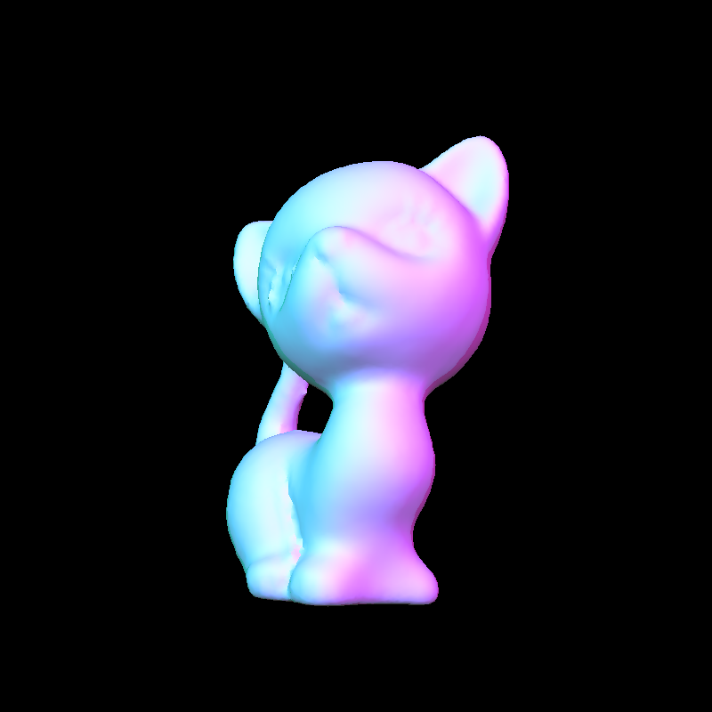
Assignment 2 - 3D Shaded Surface Renderer
Due Wednesday Oct. 23, 2019 at 3:00 PM

Overview
In this assignment, you will extend your code from Assignment 1 to write a program in C++ that reads in a description of a scene and rasterizes 3D shaded surfaces based on the objects in the scene as a PPM image output.
The graphics pipeline for this rasterization process is similar to the one that you implemented for the wireframe renderer. The difference is that we will be replacing Bresenham’s line drawing algorithm with new elements that allow rasterization of solid, colored triangles rather than simple skeletons of triangles. The new graphics pipeline still applies the same coordinate transformations from the previous pipeline (i.e. world space to camera space to normalized device coordinates), but it also makes use of interpolation via barycentric coordinates, surface normals, the lighting model, Gouraud and Phong shading, backface culling, and depth buffering to correctly color and shade all the triangular faces to obtain shaded surfaces. You will implement this entire pipeline in the assignment.
Before you begin, you may want to review the assignment material with these lecture notes. The files for this assignment can be downloaded here. More in-depth details for the assignment will be given in the sections below.
Your Assignment
As we said above, your task for this assignment is to implement the graphics pipeline for rendering scenes of shaded surfaces. The scenes for this assignment are described with an extension of the file format that you worked with in Assignment 1. Let us explain the additions to the file format with the following example file:
The file format now specifies additional parameters:
In addition, the .obj files are now in a slightly different format to account for surface normals. Let us explain with the following example file:
There are two main modifications to the .obj file format that you are used to seeing. The first is the presence of the vn lines. Just like how a v is followed by the coordinates of a vertex in the object defined by the .obj file, a vn is followed by the components of a surface normal of the object. Second, the f lines have been modified to include not only indices of vertices, but also indices of normals. Each a//b pairing specifies the index of a vertex as the integer a and the index of the surface normal for that vertex as the integer b. For instance, a line such as:
specifies a face composed of vertices 1, 8, and 2 with normals 5, 4, and 3 as the respective surface normals. Note that normal indices also start at 1, just like vertex indices. This is the standard .obj file format for defining objects with already computed surface normals.
Your task is to write a program in C++ that takes as input a file with the new scene format described above and outputs a PPM image of the specified scene (with desired and resolutions). The program should also have a “mode” argument, which can be either 0 or 1, and if it is 0, then the scene should be rendered with Gouraud shading; otherwise, the scene should be rendered with Phong shading.
The input of your program should be read from standard input as so:
xres and yres are integers that specify the and resolutions of the output image, and mode is either 0 or 1.
To help guide you, we have broken the task of writing this program into parts. We recommend that you read through all the parts carefully before you begin coding. Take some time to first plan out your code structure.
Unlike in Assignment 1, you should not immediately convert all points to normalized device coordinates (NDC) since the lighting and shading algorithms still require world coordinates in addition to NDC. Recall that the conversions from world space to camera space and ultimately to NDC should happen within the shading or rasterization algorithms. We recommend writing a function to transform points from world space to NDC, and calling that function when necessary.
Don’t forget to normalize your normals after you transform them! Remember that the lighting and shading algorithms assume unit normals.
You will probably want to use the same mapping for converting NDC into screen coordinates that you used in Assignment 1. You might also prefer to have the depth buffer as a global variable or as a member variable of your image data structure.
Call your Phong shading algorithm when the input mode is 1 to rasterize each triangle of each object-copy to produce a scene of Phong shaded surfaces.
Within the hw2 folder should be a folder called data. Inside the data folder are various scene description files in .txt format (plus the necessary .obj files) that you can use to test your program. The correct image outputs for each scene description file are also in the folder as 800x800 .png files. You can use these images to verify whether your program is working correctly.
Please do your work for this assignment in the hw2 folder of hw2.zip.
What to Submit
Before submitting, please comment your code clearly and appropriately, making sure to give details regarding any non-trivial parts of your program.
Submit a .zip or .tar.gz file containing all the files that we would need to compile, run, and test your program. In addition, please submit in the .zip or .tar.gz a README with instructions on how to compile and execute your program as well as any comments and information that you would like us to know.
We ask that you name your .zip or .tar.gz file lastname_firstname_hw2.zip or lastname_firstname_hw2.tar.gz respectively, where you replace the “firstname” and “lastname” fields with your actual first and last name.
Please submit your zip or tar.gz to moodle in the area for Assignment 2.
Written by Kevin (Kevli) Li (Class of 2016).
Links: Home Assignments Contacts Policies Resources