Figure 1: Each vertex is assigned a coordinate for a point on the texture. The texture is
then ”wrapped” onto the object with the corresponding points in the texture matching up
with the vertexes.
Assignment 4 Lecture Notes
By default, OpenGL only calculates lighting at vertices, and then interpolates the colors at each pixel on the triangle. With this technique, undesirable artifacts of the mesh representation are quite obvious, especially in specular highlights. Gourad shading is a form of per-vertex lighting and is very similar to the default lighting model used by OpenGL. On the other hand, Phong shading calculates the lighting for each pixel in a polygon. This is a form of per-pixel lighting and can be implemented using OpenGL shaders.
GLSL is a high-level language for writing GPU programs. There are two types of shaders in GLSL, vertex shaders and fragment shaders. These shaders override parts of the default OpenGL pipeline. Since the shaders are replacements for parts of the default pipeline, you sometimes must reimplement the functionality included in the default parts.
Vertex shaders are responsible for all per-vertex calculations. The default pipeline converts vertices from object space to NDC and performs per-vertex lighting and texture coordinate calculations.
Fragment shaders are responsible for all per-pixel calculations. The OpenGL rasterizer automatically interpolates all per-vertex data for each pixel. The default pipeline simply sets output color of the pixel to the interpolated vertex color.
GLSL has very similar syntax to C. The main function is the entry point for both vertex and fragment shaders. The language includes builtin support for vector and matrix operations.
This reference describes all of the built-in functions and variables.
GLSL types:
GLSL functions:
GLSL includes built-in variables that are used to pass data into and out of the shader.
Vertex Shader Built-in Variables:
Vertex Shader Outputs
Pixel Shader
Both Shader Variables:
GLSL also has special keywords to declare other variables to pass data in or out of the shader. Uniform allows the program to specify a value that will be readable by the shader programs for each vertex and fragment. Attribute allows values to be provided to the shader per vertex. Varying declares data per vertex that will be interpolated automatically for each pixel and passed to the fragment shader. Attributes can’t be defined in the fragment shader.
| keyword | Source | Destination | Interpolation |
| uniform | CPU | Fragment + Vertex shaders | per pass |
| attribute | CPU | Vertex shader | per vertex |
| varying | Vertex shader | Fragment shader | per pixel |
Sample vertex and fragment shaders:
CPU code:
For many shading tasks, it is easiest to perform all of the calculations in camera space, with the eye at the origin of the space. OpenGL provides the builtin gl_ModelViewMatrix and gl_NormalMatrix variables for this purpose. As in Assignment 2, the normal vectors must be transformed with a different transformation in order to remain normal to transformed surfaces.
Part 2: Texturing and Normal Mapping
Texturing is used to get much more detail out of rendering, than just from the vertex data alone. A very common application of (multi)texturing is the use of a combination of a normal map texture and a color texture to render in ’3D’ on a completely flat surface.
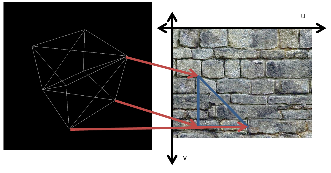
Texture mapping is a way to apply surface detail from a raster image to a 3D model. A texture map is applied (mapped) to the surface of a shape or polygon. This process is akin to applying patterned paper to a plain white box. Every vertex in a polygon is assigned a texture coordinate. Image sampling locations are then interpolated across the face of a polygon to produce a visual result.
Figure 1: Each vertex is assigned a coordinate for a point on the texture. The texture is
then ”wrapped” onto the object with the corresponding points in the texture matching up
with the vertexes.
If texture coordinates are linearly interpolated in screen space, this results in a distortion of the texture for triangles at an angle to the screen that can be seen as a discontinuity between adjacent triangles. This is not particularly apparent when interpolating colors, but is often very obvious when interpolating texture coordinates depending on the texture. Perspective correct texturing accounts for the 3D position of the triangle, and produces a correct visual effect. This is accomplished by linearly interpolating the value divided by the depth of the vertices, then multiplying by the depth of the corresponding pixel. OpenGL interpolation automatically performs perspective-correct interpolation.
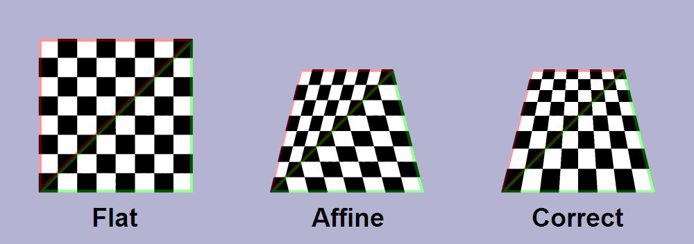
Figure 2: Linearly interpolating texture coordinates results in noticeable artifacts for
polygons at an angle to the screen. Perspective correct interpolation corrects for this effect.
GLSL has built-in capabilities for mapping textures to the surface of objects and sampling those textures. In the fragment shader we can write gl_TexCoord[0] = gl_MultiTexCoord0; This takes the per-vertex texture coordinates and stores them in a builtin varying array that will be interpolated for the fragment shader. In the fragment shader we declare uniform sampler2D texture; which will be set by the C++ program. In order to access the corresponding texture color for a pixel, we just need to color = texture2D(texture, gl_TexCoord[0].st); in GLSL. OpenGL assigns coordinates from 0 to 1 for points in a rectangular texture. If a texture should cover an entire face, the texture coordinates for the vertexes should be 0 and 1 for u and v.
For normal mapping, we use 2 textures, one for the color of the material, and another texture as the normal map. The normal map is generally used to hold fine 3D details that would be very computationally expensive to include in the polygon mesh.
A normal map takes the components of the surface normals and directly stores them in the RGB values of the texture. Since the RGB values of the normal map are in the range , you will need to map them to and re-normalize the normal. Instead of using the mesh normals for lighting calculations, we use the normal vector from the normal map. This creates the impression of fine 3D texture on the surface.
The normal vector is in the coordinate system of the flat surface the texture is mapped onto. In order to calculate lighting, we must either transform the normal into camera space, or transform the lights and camera into the surface coordinates. We can easily transform between these two coordinate systems with a tangent binormal normal (TBN) matrix. The tangent is a vector along the surface in the direction of the texture, and the binormal is in the direction.
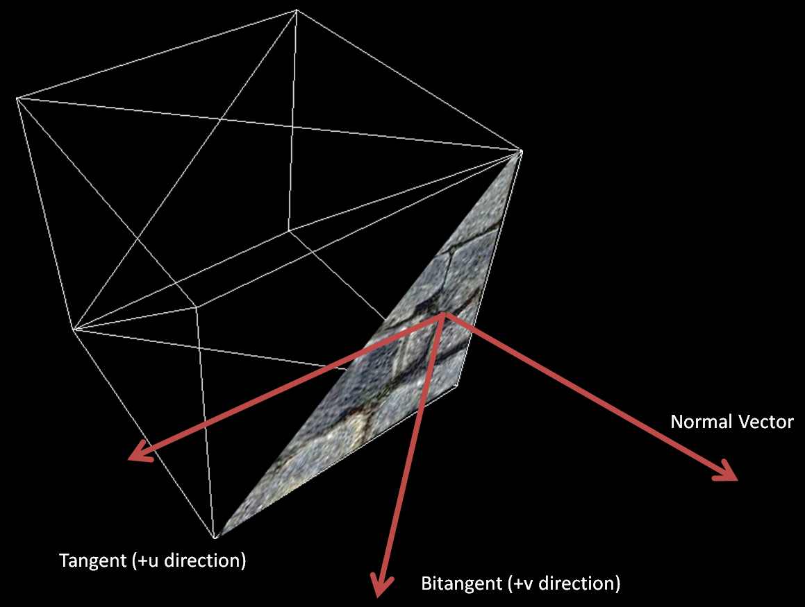
Figure 3: The tangent vector is a vector in the u direction of the texture tangent to the
surface. The binormal is also tangent to the surface but in the v direction. Together, the
tangent, binormal, and normal form a coordinate system on the surface of the object. The
binormal is also called the bitangent, since it is also tangent to the surface plane.
The following is the formula for our TBN matrix:
where is the vector in the camera frame and is the vector in the surface frame. are the tangent, binormal, and normal vectors in camera space.
This matrix is equivalent to taking the dot product for each component with , projecting the original vector onto each axis of the new coordinate system:
![]()
Figure 4: In order to transform a vector into a new coordinate system, each component is
just equal to the dot product of the vector with the unit vector of each axis of the new
coordinate system. This is shown with a 2D coordinate transform above.
OpenGL gives the normal vector for each vertex as a builtin. For the tangent, an OpenGL attribute must be defined in the CPU code and set for each vertex. In general, the tangent can be computed from the normal and the texture coordinates, but is often already generated when a texture is first created for an object. Many proprietary formats for 3D models include specification for texture tangent vectors. The binormal is a third orthogonal vector, so it can just be calculated as the cross product of the normal and tangent.
The camera and light vectors should be calculated and transformed into surface space by the vertex shader. These values can be stored as varying, and the interpolated values can be accessed from the fragment shader. The surface normal for each pixel should be sampled from the normal map, and the final color value can be calculated then.
Original assignment by Andrew Zhao (Class of 2016).
Updated by Brian Lee (Class of 2018).
Links: Home Assignments Contacts Policies Resources